create 3d mesh from drawing
Update note: Sean Duffy updated this tutorial for Unity 2019.1.two. Arai Lanju wrote the original.
Welcome to the world of 3D objects and mesh manipulation! I of the benefits of using Unity as your game development platform is its powerful 3D engine. That 3D engine, along with Unity's ability to employ custom editors, makes the evolution of 3D games and apps so much easier.
With the growth of virtual reality and augmented reality (VR/AR) applied science, most developers volition inadvertently observe themselves wrestling with the gritty bits of 3D concepts. So let this tutorial be your starting point. Don't worry, there will exist no complicated 3D math here — merely lots of hearts, drawings, arrows and loads of fun!
Note: This tutorial is intended for users who are familiar with the Unity editor and take some experience with C# programming. If you need to brush up on these topics, check out Introduction to Unity UI and Introduction to Unity Scripting get-go.
Y'all need to have at least Unity 2019.1.3 installed. Y'all can download the latest version of Unity here.
This tutorial uses a custom editor. Yous can larn more well-nigh custom editors at Extending the Unity Editor.
Getting Started
Agreement Meshes
Time to showtime with the basic vocabulary of 3D rendering. The shape of a 3D object is defined past its mesh. A mesh is like a net of points, or vertices. The invisible lines that connect these vertices form triangles, which ascertain the basic shape of the object.

But in addition to the shape, the engine needs to know how to draw the surface of the object. So a mesh'southward information also includes its normals, which are vectors that determine which way a particular triangle is facing, and thus how light bounces off of information technology. Finally, a UV Map maps a material to an object, specifying how textures wrap effectually the shape.
In Unity, in that location are two master rendering components: The Mesh Filter, which stores the mesh data of a model, and the Mesh Renderer, which combines the mesh data with materials to render the object in the scene.
Got all that? Here's a cheat sheet for easy reference:
- Vertices: A vertex is a point in 3D space. Ofttimes abbreviated to "vert".
- Lines/Edges: The invisible lines that connect vertices to i another.
- Triangles: Formed when edges connect three vertices.
- UV Map: Maps a material to an object, specifying how textures wrap around the object's shape.
- Normals: The directional vector of a vertex or a surface. This characteristically points outward, perpendicular to the mesh surface, and helps determine how light bounces off of the object.
- Mesh: Holds all the vertices, edges, triangles, normals and UV data of a model.
Hither are the bones steps (in pseudocode) to create a 3D mesh:
- Create a new mesh named "myMesh".
- Add data to myMesh's vertices and triangle properties.
- Create a new mesh filter named "myMeshFilter".
- Assign myMesh to myMeshFilter's mesh property.
Setting Upwards the Project
Now that yous have the basics covered, download the project using the Download Materials push at the top or bottom of this page, then unpack the files and open the starter projection in Unity. Check out the folder structure in the Project view:

- Prefabs: This contains a CustomHeart prefab, which you'll use to save your 3D mesh at runtime.
- Scenes: This contains the iii scenes that yous will use for the different parts of this tutorial.
- Editor: The scripts inside this folder give you lot special powers in the editor during development.
- Scripts: This contains runtime scripts, or components. When yous attach these components to a GameObject, they'll execute when yous click Play.
- Materials: This binder contains the textile for the mesh y'all'll be working with.
In the side by side department, you lot will create a custom editor to visualize the parts of a 3D mesh.
Poking and Prodding Meshes With a Custom Editor
Open 01 Mesh Study Demo inside RW/Scenes. In the Scene view, you will see a humble cube:

You're going to build a custom editor to tear this poor cube apart! (And then you'll larn how to keep it in one piece.)
Customizing the Editor Script
Select the Editor folder in the Projection view. Scripts in this special folder modify how the Unity editor works; they exercise not go part of the congenital game.

Open MeshInspector.cs and view the source code. Notation that this form inherits from Unity'south base Editor grade — that'south what makes Unity understand this is a custom editor rather than a game script.
The commencement step is to tell Unity what kind of objects that this special editor should draw. Add this attribute on the line higher up the MeshInspector grade proclamation:
[CustomEditor(typeof(MeshStudy))] Now, when whatsoever GameObject with the Mesh Study component attached to it is visible in the Scene view, this grade will handle drawing information technology. But correct now, yous won't know if that's happening.
OnSceneGUI is an upshot method that Unity calls every time it renders the Scene view in the editor. Information technology'due south your chance to change how Unity draws your object in the scene. Add the following at the beginning of OnSceneGUI:
mesh = target as MeshStudy; Debug.Log("Custom editor is running"); The base of operations Editor grade provides a reference to the object y'all're customizing in the target variable, which has type Object. Yous can't do much that'due south useful with a apparently vanilla Object, so this code casts target as the blazon MeshStudy. Logging a message allows you to come across in the console that the custom editor is indeed running.
Save the file and return to Unity. Go to the RW/Scripts folder and elevate MeshStudy.cs onto the Cube GameObject in the Hierarchy to adhere the component to it.

Look in the console and brand sure your lawmaking is running. Then become ahead and remove the Debug.Log line then it doesn't alluvion your console.
Cloning a Mesh
When you lot're working with a 3D mesh with a custom editor in Edit mode, it is easy to accidentally overwrite Unity's default mesh — that is, the born Sphere, Cube, Cylinder and and then on. If that happens, yous'll need to restart Unity.

To avoid this, you'll clone the mesh before making any changes to it in Edit manner.
Open MeshStudy.cs. This script inherits from MonoBehaviour, so its Start will not run in Edit mode. Luckily, that'due south easy to set up!
In MeshStudy, to a higher place the course declaration, add the following:
[ExecuteInEditMode] When a form has this attribute, its Offset will fire in both Play manner and Edit mode. At present that yous've added it, y'all can instantiate and clone your mesh object before changing anything.
Add the following code to InitMesh:
meshFilter = GetComponent<MeshFilter>(); originalMesh = meshFilter.sharedMesh; //ane clonedMesh = new Mesh(); //2 clonedMesh.name = "clone"; clonedMesh.vertices = originalMesh.vertices; clonedMesh.triangles = originalMesh.triangles; clonedMesh.normals = originalMesh.normals; clonedMesh.uv = originalMesh.uv; meshFilter.mesh = clonedMesh; //3 vertices = clonedMesh.vertices; //4 triangles = clonedMesh.triangles; isCloned = true; //five Debug.Log("Init & Cloned"); Here's what's happening:
- Grabs whatever mesh you've originally assigned in
MeshFilter. - Creates a new mesh case called
clonedMeshand sets its properties by copying the first mesh. - Assigns the copied mesh back to the mesh filter.
- Updates local variables, which you'll need later.
- Sets
isClonedtotrue; you'll reference this after.
Save the file and return to Unity. The console should bear witness the message "Init & Cloned".
Select Cube in the Hierarchy and look at the Inspector. The Mesh Filter will show a mesh named clone. Dandy! This means you take cloned the mesh successfully.

But discover in that location's no new Mesh asset in your project — the cloned mesh but lives in Unity'due south retention right now, and it will disappear if y'all close the scene. Yous'll learn how to save a Mesh later.
Resetting a Mesh
For now, yous want to give yourself an piece of cake way to reset your mesh then you can play around without fear. Become back to MeshInspector.cs.
OnInspectorGUI lets you customize the Inspector for your object with actress GUI elements and logic. In OnInspectorGUI, find the comment //draw reset button and replace information technology with the following:
if (GUILayout.Push button("Reset")) //1 { mesh.Reset(); //two } - This code draws a Reset push button in the Inspector. The draw function returns
truthfulwhen it's pressed. - When pressed, the push calls
Resetin MeshStudy.cs.
Save the file and return to MeshStudy.cs. Add the following to Reset:
if (clonedMesh != nix && originalMesh != null) //one { clonedMesh.vertices = originalMesh.vertices; //2 clonedMesh.triangles = originalMesh.triangles; clonedMesh.normals = originalMesh.normals; clonedMesh.uv = originalMesh.uv; meshFilter.mesh = clonedMesh; //iii vertices = clonedMesh.vertices; //4 triangles = clonedMesh.triangles; } Here'southward what this code does step-past-pace:
- Checks that both the original mesh and the clone mesh exist, in case the object's mesh filter doesn't have any data in it.
- Resets all the properties of
clonedMeshto those of the original mesh. - Assigns
clonedMeshdorsum to the Mesh Filter component. - Updates local variables.
Save the file and return to Unity.
In the Inspector, click on the Test Edit button to mess with the cube'southward mesh, and so press the Reset push button to restore information technology.

Understanding Vertices and Triangles With Unity
As you saw earlier, a mesh consists of vertices connected past edges to form triangles. Triangles define the basic shape of the object.
Notation: Unity's Mesh grade keeps track of vertices and triangles with 2 arrays:
- It stores vertices equally an array of
Vector3. - It stores triangles equally an array of integers. Each integer is the index of 1 of the vertices in the verts array, and each grouping of three sequent integers represents one triangle.
For example, the group
triangles[0], triangles[1], triangles[2]represents ane triangle, the grouptriangles[3], triangles[four], triangles[5]represents the next triangle and so on.
And so, in a simple Quad mesh that consists of four vertices and two triangles, the Quad's mesh data would be:

Visualizing Vertices
It volition exist easier to see how this works if you can draw and move around the vertices on a mesh with handles. Handles are tools for working with objects in the Scene view, like the draggable sphere for the Rotate tool. Now, y'all're going to write your ain handle!
In MeshInspector.cs, look for EditMesh and add together the following:
handleTransform = mesh.transform; //1 handleRotation = Tools.pivotRotation == PivotRotation.Local ? handleTransform.rotation : Quaternion.identity; //2 for (int i = 0; i < mesh.vertices.Length; i++) //3 { ShowPoint(i); } - Gets the mesh'due south transform, which you'll need to know where to draw the vertices in world space.
- Gets the current pivot Rotation mode, to draw the handle the same way as everything else in the scene.
- Loops through the mesh'southward vertices and draws dots with
ShowPoint.
In ShowPoint, replace the //describe dot comment with:
Vector3 signal = handleTransform.TransformPoint(mesh.vertices[alphabetize]); //1 Handles.color = Color.blue; point = Handles.FreeMoveHandle(point, handleRotation, mesh.handleSize, Vector3.goose egg, Handles.DotHandleCap); //2 - This line converts the vertex's local position into world infinite.
- Draws the dot using the
Handlesutility class.
Handles.FreeMoveHandle makes an unconstrained movement handle, which you lot volition utilize in the next section to enable dragging the points around.
Save the file and render to Unity.
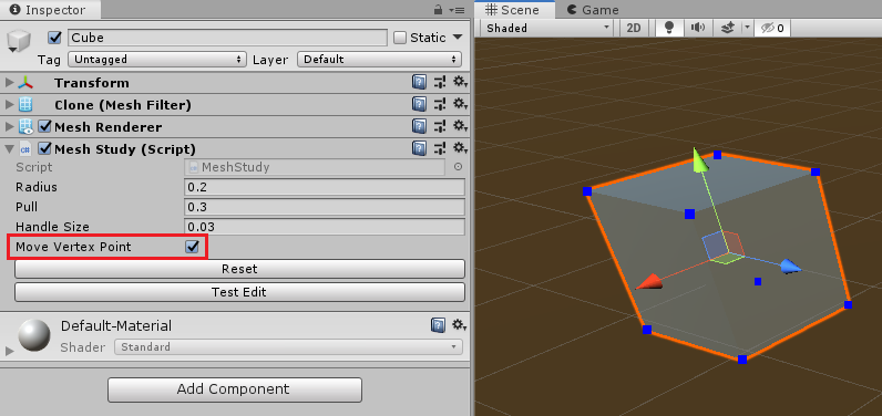
Cheque the Cube's MeshInspector and make sure that you've checked Motility Vertex Point.
You lot should now see the vertices of the mesh marked with blue dots on screen. Try attaching the script to other 3D objects and run across the results for yourself! :]
Moving a Single Vertex
Yous'll start with the nigh basic kind of mesh manipulation: Moving a single vertex.
Open up MeshInspector.cs. Within ShowPoint, replace the //drag comment with the following:
if (GUI.changed) //3 { mesh.DoAction(index, handleTransform.InverseTransformPoint(betoken)); //iv } -
GUI.inversemonitors whatsoever changes made to the dots, which works nicely withHandles.FreeMoveHandleto detect a dragging activeness. - On dragging a vertex, call
mesh.DoActionwith the alphabetize of the vertex and the vertex's position as parameters. This line also converts the vertex's position back to local space withInverseTransformPoint.
Salve MeshInspector.cs and go to MeshStudy.cs. Add the post-obit in DoAction:
PullOneVertex(index, localPos); Then add the following to PullOneVertex:
vertices[index] = newPos; //ane clonedMesh.vertices = vertices; //two clonedMesh.RecalculateNormals(); //3 - Updates the target vertex's position.
- Assigns the updated vertices assortment back to the cloned mesh.
- Tells Unity to re-depict the mesh to reflect the alter.
Save the script and return to Unity. Attempt dragging one of the dots on the cube.

Information technology seems like some of the vertices share the aforementioned position, and then when you lot pull only one, the other vertices stay backside and your mesh breaks. You'll learn how to fix this problem shortly. :]
Looking at the Vertices Array
Visually, a cube mesh consists of eight vertices, six sides and 12 triangles. Time to meet if Unity agrees.

Go to MeshStudy.cs, and earlier Start, expect for a variable named vertices. Yous'll see that it has the [HideInInspector] attribute.
Temporarily annotate out that attribute for a quick peek into the assortment:
//[HideInInspector] public Vector3[] vertices; Note: More than complicated 3D meshes tin can have thousands of vertices. Unity will freeze up if it tries to show all those values in the Inspector, so in general, you'll hide the assortment with [HideInInspector]. You lot're just peeking!
Salve the file, render to Unity and look at your cube. You can now see the vertices property on Mesh Report. Click on the arrow icon abreast it to show the assortment of Vector3 elements.

You tin see that the array size is 24, which ways that there are definitely vertices sharing the aforementioned position! Have a moment and think almost why in that location might exist multiple vertices in the aforementioned identify.
[spoiler title = "Why 24 Vertices?"]
The simplest answer is:
A cube has 6 sides and each side has 4 vertices that class a plane. six × 4 = 24 vertices.
There are other means to think about this, if this is hard to grasp. Only for now, just know that some meshes will have vertices that share the aforementioned position.

[/spoiler]
Since you lot're washed peeking into the verts array, go ahead and uncomment [HideInInspector].
Finding All Like Vertices
You can meet that manipulating a mesh is going to accept more than than just moving single vertices — you take to move all the vertices for a particular signal in space in club to go on the mesh together. So you're now ready to unbreak your heart, er, mesh.
In MeshStudy.cs, supervene upon all the lawmaking within DoAction with:
PullSimilarVertices(index, localPos); Get to PullSimilarVertices and add together the post-obit:
Vector3 targetVertexPos = vertices[index]; //1 List<int> relatedVertices = FindRelatedVertices(targetVertexPos, false); //2 foreach (int i in relatedVertices) //iii { vertices[i] = newPos; } clonedMesh.vertices = vertices; //4 clonedMesh.RecalculateNormals(); - Gets the target vertex position from the
verticesarray. - Finds all the vertices that share the same position every bit the target vertex and puts their indices into a list.
- Loops through that listing and updates the position of all related vertices.
- Assigns the updated
verticesdorsum toclonedMesh.vertices, so redraws the mesh.
Save the file and return to Unity. Click and elevate any of the vertices; the mesh should at present retain its course without breaking.

Save the scene. Yous've taken the first step towards existence a mesh magician!
Manipulating Meshes
Editing meshes in Unity is fun, but what if you lot could add some "squish" to your game past deforming meshes at runtime? Next, y'all'll try that out in its near bones form — pushing and pulling some predefined vertices.

No math...
Collecting the Selected Indices
You'll start by making a custom editor that lets yous select the vertices to move around in real time. Open upward the 02 Create Heart Mesh scene within RW/Scenes. Yous'll see a red sphere in the Scene view.

Select the Sphere in the Hierarchy and look at the Heart Mesh component. This is the script that volition store the verts you select.
But right at present, in that location aren't whatever verts shown in the scene. So adjacent, you're going to set that!
Open RW/Editor/HeartMeshInspector.cs. In ShowHandle, within the if statement, add the post-obit lawmaking:
Handles.color = Color.blue; if (Handles.Push button(point, handleRotation, mesh.pickSize, mesh.pickSize, Handles.DotHandleCap)) //1 { mesh.selectedIndices.Add together(index); //2 } - This makes Unity draw the vertices of the mesh as buttons, then you can click on them.
- When you click the button, information technology adds the selected index to the
mesh.selectedIndiceslist.
Add the post-obit code at the finish of OnInspectorGUI, after the existing if statement:
if (GUILayout.Button("Clear Selected Vertices")) { mesh.ClearAllData(); } This adds a custom Reset button in the Inspector. Side by side, you'll write the code to clear out your selection.
Salve the file and open RW/Scripts/HeartMesh.cs. In ClearAllData, add the following:
selectedIndices = new List<int>(); targetIndex = 0; targetVertex = Vector3.zero; This clears the values in the selectedIndices list and sets targetIndex to zero. It also resets the targetVertex position.
Save the file and return to Unity. Select the Sphere and expect at its HeartMesh component. Make sure yous've checked Is Edit Mode and so you can meet the mesh'due south vertices in the Scene view. And so click on the arrow icon next to Selected Indices to testify the array.
Click on a few blue dots and watch new entries appear in Selected Indices. Try out your Clear Selected Vertices push button to make sure information technology clears all values correctly.

Annotation: You have the selection to show/hibernate the transform handle with Prove Transform Handle in the custom Inspector, since it can go far the fashion of selecting verts. Only remember not to panic when you find the Transform handle missing from your other scenes! Exist sure to switch information technology back on before you exit.
Deforming the Sphere Into a Heart Shape
Updating mesh vertices in existent time requires three steps:
- Copy the electric current mesh vertices (before blitheness) to
modifiedVertices. - Do calculations and update values on
modifiedVertices. - Copy
modifiedVerticesto the current mesh on every stride alter and become Unity to redraw the mesh.
Go to HeartMesh.cs and add together the post-obit variables before Offset:
public bladder radiusOfEffect = 0.3f; //1 public float pullValue = 0.3f; //ii public bladder duration = 1.2f; //3 int currentIndex = 0; //iv bool isAnimate = fake; float startTime = 0f; float runTime = 0f; Moving a vertex should have some influence on the vertices around information technology to maintain a smooth shape. These variables control that effect.
- Radius of area affected by the targeted vertex.
- The forcefulness of the pull.
- How long the blitheness will run.
- Electric current index of the
selectedIndiceslist.
In Init, before the if statement, add together:
currentIndex = 0; This sets currentIndex — the first index of the selectedIndices list — to 0 at the beginning of the game.
Still in Init, earlier the closing braces of the else statement, add:
StartDisplacement(); StartDisplacement is what actually moves the vertices. It only runs when isEditMode is simulated.
Right at present, this method does nothing, so add the following to StartDisplacement:
targetVertex = originalVertices[selectedIndices[currentIndex]]; //1 startTime = Fourth dimension.time; //ii isAnimate = true; - Singles out the
targetVertexfrom theoriginalVerticesarray to get-go the animation. Remember, each assortment item is a Listing of integer values. - Sets the kickoff time to the electric current time and changes
isAnimatetotrue.
After StartDisplacement, create a new method called FixedUpdate with the following lawmaking:
protected void FixedUpdate() //1 { if (!isAnimate) //2 { return; } runTime = Time.fourth dimension - startTime; //3 if (runTime < duration) //4 { Vector3 targetVertexPos = meshFilter.transform.InverseTransformPoint(targetVertex); DisplaceVertices(targetVertexPos, pullValue, radiusOfEffect); } else //v { currentIndex++; if (currentIndex < selectedIndices.Count) //6 { StartDisplacement(); } else //seven { originalMesh = GetComponent<MeshFilter>().mesh; isAnimate = simulated; isMeshReady = truthful; } } } Here's what the code is doing:
- The
FixedUpdatemethod runs on a fixed interval, pregnant that it'southward frame rate contained. Read more near it here. - If
isAnimateis imitation, it won't do annihilation. - Keeps track of how long the animation has been running.
- If the animation hasn't been running likewise long, it continues the animation past getting the world space coordinates of
targetVertexand callingDisplaceVertices. - Otherwise, fourth dimension'south up! Adds i to
currentIndexto start processing the animation for the next selected vertex. - Checks if all the selected vertices have been processed. If non, calls
StartDisplacementwith the latest vertex. - Otherwise, you've reached the stop of the listing of selected vertices. This line makes a re-create of the current mesh and sets
isAnimatetofalseto cease the animation.
Making the Vertices Move Smoothly
In DisplaceVertices, add together the following:
Vector3 currentVertexPos = Vector3.zero; float sqrRadius = radius * radius; //1 for (int i = 0; i < modifiedVertices.Length; i++) //2 { currentVertexPos = modifiedVertices[i]; float sqrMagnitude = (currentVertexPos - targetVertexPos).sqrMagnitude; //3 if (sqrMagnitude > sqrRadius) { continue; //4 } bladder altitude = Mathf.Sqrt(sqrMagnitude); //5 float falloff = GaussFalloff(distance, radius); Vector3 interpret = (currentVertexPos * force) * falloff; //half dozen translate.z = 0f; Quaternion rotation = Quaternion.Euler(translate); Matrix4x4 grand = Matrix4x4.TRS(translate, rotation, Vector3.ane); modifiedVertices[i] = m.MultiplyPoint3x4(currentVertexPos); } originalMesh.vertices = modifiedVertices; //7 originalMesh.RecalculateNormals(); This code loops over every vertex in the mesh and displaces those that are shut to the ones y'all selected in the editor. It does some math tricks to create a shine, organic outcome, like pushing your thumb into clay. You'll acquire more than almost this afterward on.
Hither'south a closer look at what this lawmaking does:
- Gets the foursquare of the radius.
- Loops through every vertex in the mesh.
- Finds the distance between the current vertex and the target vertex and squares it.
- If this vertex is outside the area of consequence, exits the loop early and continues to the next vertex.
- Otherwise, calculates the
falloffvalue based on the distance. Gaussian functions create a smooth bong bend. - Calculates how far to move based on distance, and so sets the rotation (direction of displacement) based on the result. This makes the vertex movement "outward", that is, direct away from the targetVertex, making information technology seem to puff out from the center.
- On exiting the loop, stores the updated
modifiedVerticesin the original mesh and has Unity recalculate the normals.
Save your file and return to Unity. Select the Sphere, get to the HeartMesh component, and try adding some vertices into your Selected Indices property. Plough off Is Edit style and printing Play to preview your work.

Play effectually with the Radius Of Outcome, Pull Value and Duration settings to see unlike results. When y'all are ready, update the settings per the screenshot below.

Press Play. Did your sphere balloon into a middle shape?

Congratulations! In the adjacent department, you volition learn how to salve the mesh for farther utilize.

Saving Your Mesh in Real Time
Right now, your heart comes and goes whenever you button the Play push button. If you want a love that lasts, you demand a way to write the mesh to a file.
A uncomplicated manner is to ready a placeholder prefab that has a 3D object every bit its child, then replace its mesh asset with your heart (...er, your Heart mesh) via a script.
In the Projection view, observe Prefabs/CustomHeart. Double-click the prefab to open up information technology in Prefab Editing mode.
Click on the Arrow icon to aggrandize its contents in the Hierarchy and select Kid. This is where you'll store your generated mesh.

Go out prefab editing way and open HeartMeshInspector.cs. At the terminate of OnInspectorGUI, before the closing braces, add the following:
if (!mesh.isEditMode && mesh.isMeshReady) { string path = "Avails/RW/Prefabs/CustomHeart.prefab"; //i if (GUILayout.Push("Salvage Mesh")) { mesh.isMeshReady = false; Object prefabToInstantiate = AssetDatabase.LoadAssetAtPath(path, typeof(GameObject)); //two Object referencePrefab = AssetDatabase.LoadAssetAtPath (path, typeof(GameObject)); GameObject gameObj = (GameObject)PrefabUtility.InstantiatePrefab(prefabToInstantiate); Mesh prefabMesh = (Mesh)AssetDatabase.LoadAssetAtPath(path, typeof(Mesh)); //3 if (!prefabMesh) { prefabMesh = new Mesh(); AssetDatabase.AddObjectToAsset(prefabMesh, path); } else { prefabMesh.Clear(); } prefabMesh = mesh.SaveMesh(prefabMesh); //4 AssetDatabase.AddObjectToAsset(prefabMesh, path); gameObj.GetComponentInChildren<MeshFilter>().mesh = prefabMesh; //5 PrefabUtility.SaveAsPrefabAsset(gameObj, path); //half-dozen Object.DestroyImmediate(gameObj); //7 } } Here's what the code does:
- Stores the CustomHeart prefab object asset path, which you need to be able to write to the file.
- Creates two objects from the CustomHeart prefab, one as a GameObject and the other as a reference.
- Creates an example of the mesh asset
prefabMeshfrom CustomHeart. If it finds the asset, information technology clears its data; otherwise, information technology creates a new empty mesh. - Updates
prefabMeshwith new mesh information and associates it with the CustomHeart nugget. - Updates the GameObject'southward mesh nugget with
prefabMesh. - Creates a Prefab Nugget at the given path from the given
gameObj, including whatever children in the scene. This replaces whatever was in the CustomHeart prefab. - Destroys
gameObjimmediately.
Salvage your file and go to HeartMesh.cs. Supercede the body of SaveMeshwith the post-obit:
Mesh nMesh = new Mesh(); nMesh.proper noun = "HeartMesh"; nMesh.vertices = originalMesh.vertices; nMesh.triangles = originalMesh.triangles; nMesh.normals = originalMesh.normals; render nMesh; This will return a mesh asset based on the heart-shaped mesh.
Salvage the file and render to Unity. Press Play. When the blitheness ends, a Relieve Mesh button will appear in the Inspector. Click on the button to salvage your new mesh, and then stop the player.
Discover Prefabs/CustomHeart again in the Project view and open information technology in Prefab Editing way. You will see a make spanking new heart-shaped mesh has been saved in your prefab!


Good Job!
Putting Information technology All Together
In the previous section, y'all learned how to alter a mesh by selecting individual vertices. While this is cool, you lot can exercise more than interesting things if you know how to select vertices procedurally.
In the previous scene, DisplaceVertices uses a Gaussian falloff formula to determine how much to "pull" each vertex inside the radius of the effect. Merely in that location are other mathematical functions you can use to calculate the 'fall off' bespeak; that is, where the pull strength starts decaying. Each function produces a dissimilar shape:


Like cupcake toppings...
In this section, you will acquire how to dispense vertices using a calculated curve.
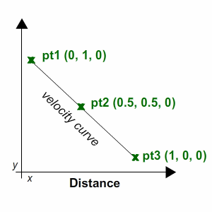
Based on the principle that velocity equals distance divided past fourth dimension (v=(d/t)), you tin can make up one's mind the vector'southward position by referencing its altitude divided past its time cistron.
Using the Curve Method
Salvage your electric current scene, and then open 03 Customize Heart Mesh from the Scenes folder.
Notice the example of your CustomHeart prefab in the hierarchy and click on the arrow icon next to it to expand its content. Select the Kid object.
View its properties in the Inspector. Yous'll come across Mesh Filter with the Middle Mesh asset. Attach Custom Heart to Kid. The asset should now change from HeartMesh to clone.

Open CustomHeart.cs and add the following correct above Start:
public enum CurveType { Curve1, Curve2 } public CurveType curveType; Curve bend; This creates a public enum named CurveType and makes it bachelor in the Inspector.
Go to CurveType1 and add together the following:
Vector3[] curvepoints = new Vector3[iii]; //one curvepoints[0] = new Vector3(0, 1, 0); curvepoints[1] = new Vector3(0.5f, 0.5f, 0); curvepoints[two] = new Vector3(i, 0, 0); curve = new Bend(curvepoints[0], curvepoints[1], curvepoints[ii], false); //two What'south going on?
- The basic curve consists of three points. This code sets and plots the points for the first curve.
- Generates the first curve with
Curveand assigns its values tocurve. You tin set up the last parameter totrueto describe the curve every bit a preview.
Now go to CurveType2 and add the post-obit:
Vector3[] curvepoints = new Vector3[3]; //1 curvepoints[0] = new Vector3(0, 0, 0); curvepoints[1] = new Vector3(0.5f, 1, 0); curvepoints[2] = new Vector3(1, 0, 0); curve = new Curve(curvepoints[0], curvepoints[one], curvepoints[2], false); //ii This works much like CurveType1.
- Sets and plots the points for the second curve.
- Generates the second bend with the
Bendmethod and assigns its values tocurve.
In StartDisplacement, before the closing braces, add the post-obit:
if (curveType == CurveType.Curve1) { CurveType1(); } else if (curveType == CurveType.Curve2) { CurveType2(); } This will generate different curves depending on what you select every bit the Curve Type in the Custom Heart component.
In DisplaceVertices, within the for loop, before the closing braces, add the post-obit:
bladder increment = curve.GetPoint(distance).y * force; //one Vector3 translate = (vert * increment) * Time.deltaTime; //two Quaternion rotation = Quaternion.Euler(translate); Matrix4x4 yard = Matrix4x4.TRS(interpret, rotation, Vector3.i); modifiedVertices[i] = m.MultiplyPoint3x4(modifiedVertices[i]); This might wait familiar — information technology's much similar the lawmaking you added to HeartMesh.
- Gets the curve'south position at the given
altitudeand multiplies itsyvalue bystrengthto getincrement. - Creates a new
Vector3chosentranslateto store the new position for the current vertex and applies its Transform accordingly.
Salvage the file and return to Unity. Bank check out the properties in Custom Heart on the Child GameObject.
In the Edit Blazon driblet-downwardly menu, you lot can now select Add Indices or Remove Indices to update your list of vertices. Select None to exit Edit manner, and then click Play see the results. Experiment with dissimilar settings and vertex selections.
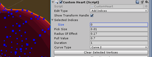
To encounter an example of the different curve types, enter these values:

Set Bend Type to Curve1, check that Edit Blazon is fix to None and printing Play.

You should encounter how the mesh fans out into a design. Move the model around to its side-view then yous tin can see the shape this curve produces. Exit Play and effort it again with Curve 2 to compare the results of both curve types:


That'southward it! Y'all tin click Clear Selected Vertices to reset the Selected Indices and experiment with your own patterns. Don't forget that there are several factors that will touch on the final shape of the mesh:
- The size of the radius.
- The spread of vertices within the area.
- The pattern position of the selected vertices.
- The method that you choose for displacement.
Where to Go From Here?
You lot can become all of the files for the last project past using the Download Materials button at the top and bottom of this tutorial.
Don't stop hither! Endeavor out more advanced techniques with Procedural Maze Generation.
I hope you take enjoyed this tutorial and found the information useful. Special credit to Jasper Movie from Catlike Coding for his swell tutorials, which helped me put together the demos for this project.

Feel costless to join the discussion forum beneath for any questions or comments!
sherrodmintwoubity.blogspot.com
Source: https://www.raywenderlich.com/3169311-runtime-mesh-manipulation-with-unity
0 Response to "create 3d mesh from drawing"
Post a Comment